

Table Of Contents
The behavior of a DC-DC converter is determined by the interaction of components that help build the circuit. Circuit analysis is a key aspect of understanding the implementation and converter output as it involves studying various quantities such as node voltages and loop currents through calculations. Read on to learn more about the basics of DC/DC converter circuits and key examples that demonstrate the circuit analysis process.
Basics of DC/DC Converter Circuits
DC/DC converters are a key aspect of energy drive research in power electronics and industrial applications. To meet the needs of multiple applications, it is important to implement them according to the requirements and understand the nuances of circuit behavior. The voltage and current relationship governs the design of the converter circuit during balancing. There are many factors that affect these values, including voltage ripple in the capacitor, current ripple caused by the inductor, and the state of balance.
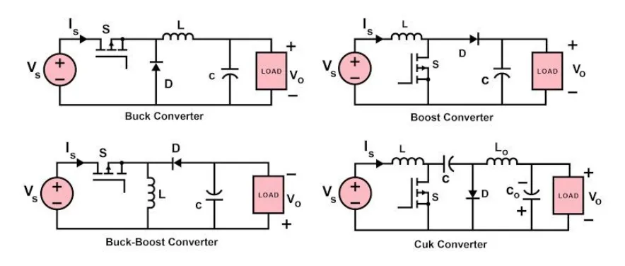
The circuit diagram of some basic DC-DC converters is shown in Figure 1. If we look closely at these circuits, most of them are composed of basic electrical components such as semiconductor switches, diodes, inductors, capacitors, and DC power supplies. The arrangement and number of these basic components vary in these circuits, so they produce different results. The general strategy of circuit analysis is to create and solve an independent set of equations to determine the design conditions or solve for basic variables. It can also be defined as determining the voltage and current of each component in the circuit.
Circuit Analysis Example
The operation mode of a DC/DC converter can be divided into two different modes based on the current flowing through the inductor [3]. When the inductor current is always greater than zero, it is said to operate in continuous conduction mode (CCM). In cases where the average inductor current is low due to low switching frequency or high load resistance, the converter is said to operate in discontinuous conduction mode (DCM).
It is important to know that CCM is the preferred mode of operation for converters due to its advantages such as increased efficiency, low number of passive components, and efficient use of semiconductor switches. Converter operation in DCM is slightly more complex and requires dynamic control. This requires determining the minimum value of the inductor in order to maintain operation in CCM.
To simplify the complexity of the circuit analysis, some approximations are made. This includes assuming that the load is resistive in nature and the DC component of the output voltage is ripple-free. In addition, the inductor and capacitor are considered pure in most cases, although it involves small ripple approximations.
Take the buck-boost converter as an example. From Figure 2, it can be seen that the polarity of the output voltage is opposite compared to the input. Considering that the capacitor is fully charged before the semiconductor switch is turned on, it is clear that once the switch is turned on, the voltage across the switch is equal to the voltage across the inductor. Furthermore, the output voltage is the same as the voltage across the capacitor. Once the switch is turned off, the voltages across the inductor and capacitor are equal in magnitude but opposite in polarity.
Key Points
Circuit analysis is a key aspect of understanding the implementation and converter output as it involves studying various quantities such as node voltages and loop currents through calculations.
The general strategy for circuit analysis is to create and solve a separate set of equations to determine the design conditions or solve for the fundamental variables.
CCM is the preferred mode of operation for converters because of its advantages such as increased efficiency, low passive device component count, and efficient use of semiconductor switches.
DC converters all work based on these basic principles. When predicting the output of a circuit, it is necessary to conduct a comprehensive analysis of the component parameters, operating mode, and load conditions in the circuit. At the same time, tools such as circuit simulation software can be used to assist in prediction and verification.
our product: